Controlling the oven's power
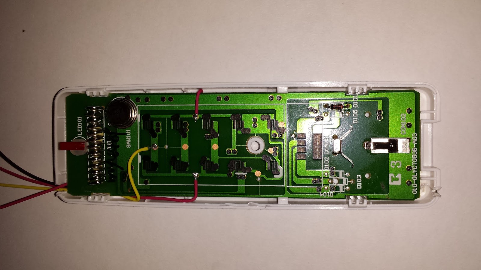
The key to building a low voltage reflow oven controller is to use a commercial, remotely controlled, wireless mains switch. The oven controller will operate the mains switch indirectly, through the wireless remote. No changes are needed to the mains switch, only to the remote control.After a short trip to the hardware store in, I came back with a Nexa wireless mains switch and its remote control. Upon taking the remote apart

it became obvious that simulating key presses should be possible by simply shorting the right pads, located underneath the rubber keys. I opted to use the two top On/Off buttons, and found the corresponding traces in the PCB, plus ground.
By not soldering onto the keys pads, and by routing the wires under the PCB, the rubber keypad can still be used, which is a bonus if you need to manually turn the mains switch off while testing your controller software.

Notice the three-pin connector on my bread board? It connects to a USB-to-GPIO cable from FTDI, allowing my simple PC controller program to drive the transistors, to simulate an 'On' or 'Off' key press.
The simplicity of my control scheme should be apparent by now:
- Plug the oven into the Nexa mains switch, and plug the Nexa mains switch into the mains outlet.
- Use the oven's knobs to set the oven to "On", and set it to maximum temperature
- The controller program (100 lines of Perl code) running on the PC monitors the ovens temperature (see below) and uses the remote control to switch the power to the oven off and on, as dictated by the desired reflow temperature profile. The 1200W oven is set to maximum temperature, and can easily exceed the temperature profile's requirement, so the role of the controller is to throttle back the heaters by cutting oven power. In practice the controller cuts oven power every 2-6 seconds, and turns it back on 2-10 seconds later, depending on the profile and temperature reading.
Reading the oven's temperature
Fine, but how to read out the oven's temperature, the control algorithm is helpless without a continuous flow of temperature readings? The choice of the C232HM cable was not completely random: the Linux MPSSE drivers can emulate SPI, which is spot on for reading termocouples via a MAX31855K. (Making the Linux MPSSE drivers work properly for SPI was actually the hardest part of the reflow oven build.....)I went the easy route, and bought a break-out board for the MAX31855K, but you could also roll your own and include the remote's transistors on the same board. Here is a shot of break-out board, the Nexa remote and the USB-to-GPIO/SPI cable, all temporarily strapped to the side of the oven for the first test run.

The end of the termocouple wire is barely visible in the above picture, secured to the blue terminal block of the break-out board. From the break-out board, the sensor end of the termocouple wire enters the heating chamber from the oven's back side, through a small hole I drilled into the corner of the heating chamber.

The oven itself is a plain toaster oven with four resistive heating elements (two in ceiling, two on the floor), costing approximately 100 USD. Underneath its outer metal cover there are no surprises. (There is no need to remove the cover for this low voltage controller build, but I did initially, just to see what my options were. Note the live heater terminals....)


Reflow results
Over the the last three year's I've successfully reflowed a dozen of my own boards using this simple apparatus. The coldest regions of the heating chamber are the corners, so I make sure I place the boards somewhere in the center of the oven. Below are a couple of pictures from the virgin run.

The uneven result for this SOIC-14 is due to the solder paste application method: I used a syringe, not a stencil, so the amount of solder paste varied from pad to pad. The large area covered by resin residue also suggests a too quick increase in temperature. This was easily fixed in the controller software (after all it's only 100 lines or so of Perl ;-) , and the oven is now an indispensable tool.
With a little bit of ingenuity, anyone can build a reflow oven without messing with mains lines. Happy reflowing!
No comments:
Post a Comment